 Inglés
 Español
Temperature Sensor Output Signal Types and Selection Guide
Temperature matters in industrial processes. Get it wrong, and you’re looking at wasted product, equipment damage, or worse. The challenge isn’t just measuring temperature accurately—it’s getting that measurement to your control system in a form it can actually use. With current loops, voltage outputs, and various digital protocols all competing for attention, picking the right signal type can feel like navigating a maze. This guide breaks down what each option actually does, where it works best, and how to match it to your specific setup.
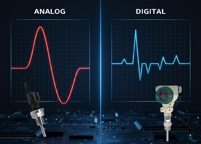
Understanding Analog Temperature Sensor Outputs
Analog temperature sensors convert physical temperature into a continuous electrical signal. These signals, typically current or voltage, vary proportionally with the measured temperature. Their continuous nature allows for fine resolution, making them suitable for applications requiring precise measurement. Analog signals are susceptible to noise over long transmission distances, often necessitating signal conditioning. Various sensors with robust analog outputs ensure reliable data acquisition in diverse industrial environments.
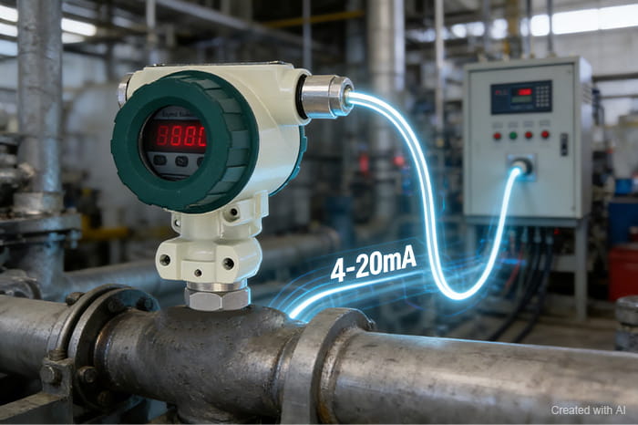
Current Loop 4 20mA Signals for Industrial Use
The 4-20mA current loop earned its reputation as an industrial standard for good reason. Current-based transmission doesn’t care much about wire resistance or voltage drops, which means you can run cables across a plant floor without losing accuracy. The “live zero” at 4mA is particularly clever. If your reading drops to 0mA, something’s broken. A sensor failure or cut wire shows up immediately rather than masquerading as a cold temperature reading.
Voltage 0 10V Signals and Their Application Scope
Voltage output signals offer simplicity that appeals to many system designers. Wire a 0-10V sensor to an analog input, and you’re reading temperature. No loop power calculations, no worrying about whether your transmitter can handle the load. The tradeoff shows up when you start running longer cables. Voltage drops across wire resistance, and electromagnetic interference couples more easily into voltage signals than current loops. Keep 0-10V sensors close to their receiving equipment. Inside a control panel or within a few meters of the PLC, they work fine. Stretch that distance, and accuracy suffers.
| Analog Signal Type | Ventajas | Disadvantages | Aplicaciones típicas |
|---|---|---|---|
| 4-20mA Current Loop | Excellent noise immunity, long transmission distance, fault detection via live zero | Requires loop power supply, slightly more complex wiring | Process control, remote installations, harsh environments |
| 0-10V Voltage | Simple implementation, direct interface with many controllers | Signal degradation over distance, more susceptible to EMI | Local control panels, short-distance applications, clean environments |
Exploring Digital Temperature Sensor Outputs
Digital temperature sensors sidestep many analog headaches entirely. Once temperature converts to digital data, noise becomes a non-issue. Either the data arrives intact, or error checking catches the problem. Beyond noise immunity, digital protocols open up capabilities that analog signals simply cannot match.
Modbus and HART Protocols for Smart Sensor Integration
Modbus RTU runs on RS485 physical layer, allowing multiple devices on a single twisted pair. One communication cable can serve dozens of sensors, each with its own address. HART takes a different approach, piggybacking digital communication on top of a standard 4-20mA signal. Your control system sees the familiar current loop while a HART communicator or compatible input card accesses configuration parameters, diagnostic data, and secondary measurements. This dual nature makes HART particularly useful when upgrading existing installations.
The Benefits of IO Link for Simplified Connectivity
IO-Link brings plug-and-play thinking to industrial sensors. Connect a sensor, and the master device automatically recognizes it, downloads stored parameters, and starts communicating. Replace a failed sensor with an identical unit, and those parameters transfer automatically. No technician with a laptop required. The PWL-U202 Small Blind Spot Ultrasonic Level Transmitter demonstrates this approach with RS485-Modbus RTU/TCP and HART outputs. While not specifically a temperature sensor, it illustrates how modern industrial instruments are moving toward richer communication that simplifies commissioning and maintenance.
Key Factors for Temperature Sensor Output Selection
Picking a signal type without considering your actual installation is asking for trouble. Several factors determine whether a particular output will work well or create ongoing headaches.
- Control System Compatibility. Check what your PLC, DCS, or data acquisition system actually accepts. Analog input cards handle 4-20mA or 0-10V. Digital communication requires appropriate interface modules. Mismatches mean additional converters, added cost, and more potential failure points.
- Transmission Distance. Current signals travel hundreds of meters without degradation. Voltage signals struggle beyond 15-30 meters in typical industrial environments. RS485 Modbus reaches 1200 meters under ideal conditions. Know your cable runs before committing to a signal type.
- Environmental Conditions. Variable frequency drives, welding equipment, and high-voltage switchgear all generate electromagnetic interference. Current loops and digital protocols handle this better than voltage signals. In severe cases, fiber optic converters may be necessary.
- Required Accuracy and Resolution. Digital outputs eliminate analog-to-digital conversion errors at the receiving end. The sensor does the conversion once, and that value travels intact. For applications where every tenth of a degree matters, this can be significant.
- Cost-Benefit Analysis. A simple 0-10V sensor costs less than a smart transmitter with HART and Modbus. For monitoring a storage tank that rarely changes temperature, the simpler option makes sense. For a critical reactor vessel, the diagnostic capabilities of a smart sensor pay for themselves quickly.
- Diagnostic and Advanced Features. HART and Modbus devices can report their own health, flag calibration drift, and provide secondary measurements. This information supports predictive maintenance programs and reduces unplanned downtime.
Matching Output Signals to Control System Requirements
Integration headaches often trace back to mismatched expectations between sensor outputs and control system inputs. The PWT4209 Temperature Sensor offers 4-20mA and RS485 Modbus RTU outputs specifically because different installations have different requirements. Having both options available means the same sensor model works whether you’re connecting to a legacy analog input or a modern communication network.
Ensuring Signal Integrity in Harsh Industrial Environments
Industrial plants are not kind to electrical signals. Motors, contactors, and power electronics all generate noise that can corrupt measurements. Maintaining signal integrity requires attention to several details.
Cable selection matters more than many realize. Shielded twisted-pair cable is standard for 4-20mA signals, with the shield grounded at one end only to prevent ground loops. RS485 networks also benefit from shielding, particularly in longer runs. Route signal cables away from power wiring, and cross at right angles when crossing is unavoidable.
Grounding deserves careful thought. Ground loops create offset errors that drift with changing conditions, making them particularly frustrating to troubleshoot. Single-point grounding and galvanic isolation break these loops.
Signal conditioners and isolators add cost but protect against voltage spikes and provide clean separation between field wiring and control system inputs. In environments with significant electrical transients, this protection prevents expensive equipment damage.
Environmental factors extend beyond electrical noise. Temperature extremes affect cable insulation and connector seals. Humidity promotes corrosion. Chemical exposure degrades materials. Selecting components with appropriate IP ratings and material compatibility prevents premature failures. For hazardous locations, explosion-proof enclosures and intrinsically safe circuit designs are mandatory, not optional.
Future Trends in Temperature Sensor Output Technology
Wireless sensor networks are moving from novelty to practical deployment. WirelessHART and ISA100.11a provide industrial-grade reliability without the cost of running cable to remote locations.
Edge computing is pushing intelligence into the sensors themselves. Rather than sending raw measurements to a central system for processing, smart sensors perform calculations locally and transmit only meaningful results. This reduces network traffic and enables faster response to changing conditions.
Predictive maintenance capabilities are becoming standard in higher-end instruments. Sensors that monitor their own health and flag developing problems before they cause failures reduce unplanned downtime and maintenance costs. The data these sensors generate feeds into broader asset management systems, supporting more sophisticated maintenance strategies.
Communication protocol convergence continues. OPC UA and Ethernet/IP are gaining ground as unifying standards that work across different vendor platforms. This interoperability reduces the integration effort required when combining equipment from multiple sources.
Partner with Pokcenser Automation for Your Sensor Needs
Choosing the right temperature sensor and output signal affects your process reliability for years to come. Pokcenser Automation brings over a decade of experience to these decisions, with sensors supporting 4-20mA, 0-10V, and RS485 Modbus RTU outputs. From initial application review through installation support and ongoing service, we work to ensure your measurement systems perform as expected. Contact us at en**@*******er.com or +86 181 7515 5326 to discuss your specific requirements.
Frequently Asked Questions About Temperature Sensor Outputs
What are the common output signals for industrial temperature sensors?
Industrial temperature sensors typically use 4-20mA current loops or 0-10V voltage signals for analog transmission. Digital options include RS485 Modbus RTU and HART protocols. The choice depends on transmission distance, noise environment, and control system compatibility. Most industrial applications favor 4-20mA for its robustness, though digital protocols are increasingly common in newer installations.
How do I choose the right temperature sensor output for my application?
Start with your control system’s input capabilities. Then consider cable distance and environmental conditions. For runs over 30 meters or electrically noisy environments, 4-20mA or RS485 Modbus RTU generally outperform voltage signals. If you need diagnostic data or remote configuration, digital protocols provide capabilities that analog signals cannot match. Budget also plays a role, as simpler analog sensors cost less when advanced features aren’t necessary.
What are the advantages of different temperature sensor signal types?
4-20mA signals excel at noise rejection and long-distance transmission, with built-in fault detection through the live zero. Voltage signals offer simpler wiring for short distances. Modbus RTU enables multi-drop networks and rich diagnostic data. HART provides digital communication while maintaining compatibility with existing 4-20mA infrastructure. Each type fits particular situations better than others.

