 Inglés
 Español
Gear Flow Meters: Working Principle, Applications & Selection Guide
When a process involves thick, viscous liquids — hydraulic oil, lube oil, fuel oil, syrups, or polymer additives — most flow meter technologies struggle. Velocity-based meters such as turbine and vortex designs assume a clean, well-behaved flow profile, which high-viscosity fluids simply do not provide. This is where the gear flow meter earns its place: it is a positive displacement (PD) meter that physically traps and counts fixed volumes of liquid, making it the natural choice for high-viscosity metering across hydraulics, petroleum, chemicals, and pharmaceuticals.
This guide explains how gear flow meters work, where they perform best, where they do not, and how to select the right one for your process.
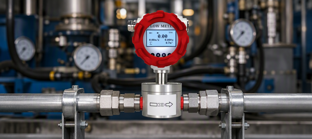
What Is a Gear Flow Meter?
A gear flow meter is a positive displacement flow meter built around two intermeshing gears — typically oval (elliptical) gears or helical gears — rotating inside a close-fitting chamber. Each rotation of the gears displaces an exact, fixed volume of liquid from the inlet to the outlet. By counting the rotations, the meter measures total volume directly; dividing by time gives flow rate.
Because the measurement is volumetric and mechanical, it does not depend on flow profile, upstream disturbances, or viscosity in the way that velocity meters do. The meter simply counts how many “slices” of liquid pass through.
How a Gear Flow Meter Works
Inside the meter, the incoming liquid pressure drives the two gears to rotate. As the gears turn, pockets of liquid are sealed between the gear teeth and the chamber wall, carried around, and discharged at the outlet. The gear rotation is sensed by a magnetic or Hall-effect pickup mounted in the meter body, which outputs a pulse for each gear tooth (or for each revolution). A flow computer, counter, or PLC converts the pulse count into volume and flow rate using the meter’s K-factor.
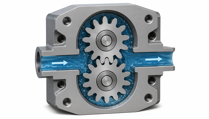
Key design variants:
- Oval gear meters: two oval gears; simple, robust, and the most common type for fuel and oil metering.
- Helical (spiral) gear meters: helical rotors provide smoother, quieter operation and handle somewhat higher pressures and a wider viscosity range.
Both variants share the same PD principle: fixed displacement per revolution, frequency output proportional to flow, and excellent repeatability.
Key Advantages of Gear Flow Meters
- Excellent accuracy on viscous liquids: typical accuracy of ±0.5% of reading across a wide viscosity range — performance that velocity meters cannot match on thick fluids.
- Outstanding repeatability: ideal for batching, dosing, and blending where consistency matters.
- Viscosity tolerance: from light solvents to very thick oils, the meter’s accuracy holds because measurement is by trapped volume, not by flow velocity.
- No straight pipe requirements: because the reading does not depend on flow profile, gear meters can be installed in tight layouts with elbows immediately upstream — a major advantage in skids and machinery.
- Good low-flow performance: PD meters maintain accuracy at low flow rates where velocity meters lose signal.
- Simple integration: pulse output connects directly to counters, PLCs, and existing batching systems.
Limitations to Keep in Mind
- Clean liquids only: the close gear clearances mean solid particles, fibers, or scale will wear the gears and eventually cause internal leakage (slippage). A strainer or filter upstream is strongly recommended.
- Not for gases or steam: PD gear meters measure liquids; gas service is handled by different technologies.
- Pressure loss: the metering chamber creates a moderate pressure drop, which must be considered in low-head systems.
- Moving parts: gears and bearings wear over time, so periodic inspection and calibration checks are part of the maintenance routine — though far less frequent than for velocity meters in the same service.
Common Applications of Gear Flow Meters
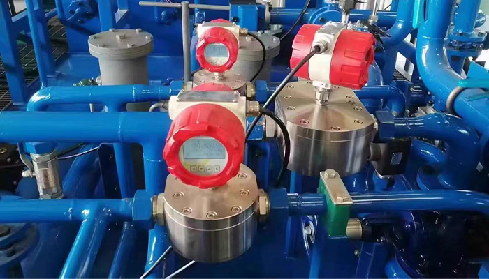
Hydraulic and lube systems. Measuring hydraulic oil consumption and lubrication flow is one of the most common gear meter duties. Meters monitor oil usage in hydraulic power units, machine tools, and circulating lube systems, supporting condition monitoring and maintenance scheduling.
Fuel metering. Diesel, gasoline, kerosene, and fuel oil transfer — including refueling, engine fuel monitoring, and burner feed — benefit from the gear meter’s accuracy and repeatability. The Pokcenser PWF-GF is engineered for petroleum duties including crude oil, diesel, and gasoline.
Chemical and petrochemical dosing. Acids, alkalis, and hydrocarbon liquids are metered with gear meters using wetted materials matched to the chemistry. The PWF-GF covers chemical media including acids, alkalis, and hydrocarbons.
Pharmaceutical and food dosing. Viscous additives, syrups, flavors, and ingredients are batched accurately with hygienic and stainless variants, supporting batch records and quality control.
How to Select a Gear Flow Meter
1. Viscosity range. Confirm the meter’s rated viscosity range covers your liquid at operating temperature. This is the first selection criterion — it decides whether a gear meter is right at all.
2. Flow range. Select a meter size so that the expected flow sits in the middle of the rated flow range. Oversizing hurts low-flow accuracy; undersizing increases pressure loss and wear.
3. Wetted materials. Match the housing and gear materials to the liquid’s chemistry and abrasive characteristics. Aluminum suits many fuels and oils; stainless steel suits chemicals, food, and pharmaceutical duty; special alloys handle aggressive media. The PWF-GF offers material options matched to petroleum, chemical, and pharmaceutical applications.
4. Pressure and temperature. Confirm the meter’s maximum working pressure and temperature exceed your operating conditions, including transients.
5. Output signal. Choose the output to fit your system: pulse output for counters and PLCs, or 4–20 mA / RS485 for analog and digital control loops.
6. Filtration. Plan a strainer or filter upstream to protect the gear mechanism from particles — it is cheap insurance for a precision instrument.
Pokcenser PWF-GF Gear Flow Meter
The Pokcenser PWF-GF gear flow meter is designed for demanding liquid metering in three core sectors: petroleum (crude oil, diesel, gasoline), chemicals (acids, alkalis, hydrocarbons), and pharmaceuticals. Built on the proven positive displacement principle, it delivers accurate, repeatable measurement for viscous liquids, with pulse output for straightforward integration into batching and control systems. For hydraulic systems, fuel transfer, and chemical dosing duties where velocity meters fall short, the PWF-GF is a dependable, cost-effective solution.
PREGUNTAS FRECUENTES
1. Can a gear flow meter measure water?
Technically yes, but a gear meter is usually not the best choice for water. Water’s low viscosity reduces the meter’s accuracy (slippage increases) and provides poor lubrication for the gears. For water service, electromagnetic or turbine meters are typically more suitable.
2. What liquids can a gear flow meter handle?
Gear meters handle liquids across a very wide viscosity range — from light fuels and solvents to high-viscosity oils, syrups, and additives — provided the liquid is clean and compatible with the wetted materials. They are not suitable for gases, steam, or liquids containing solid particles without upstream filtration.
3. Do gear flow meters require straight pipe runs?
No. Because measurement is based on trapped volume rather than flow profile, gear meters do not need upstream or downstream straight pipe. This makes them ideal for compact skids and machinery layouts where other flow meter types cannot be installed.
4. How often do gear flow meters need calibration or maintenance?
With clean media and correct sizing, gear meters run for long periods between services. Gear and bearing wear gradually increases internal slippage, so periodic flow checks against a reference are recommended; a strainer upstream significantly extends service life.
