 English
 Spanish
Turbine Flow Meters for Precision Liquid Measurement in Industry
Getting accurate liquid measurements right matters more than most people realize. A small drift in flow data can cascade into quality issues, wasted product, or control systems that never quite behave the way they should. Turbine flow meters have earned their place in industrial settings because they deliver reliable volumetric data without excessive complexity. What follows covers how these meters actually work, what affects their accuracy, how to pick the right one, and what keeps them running well over time.
How Turbine Flow Meters Actually Work
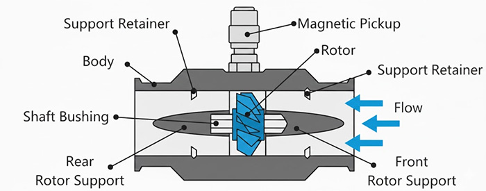
The basic idea is straightforward. Liquid flows through the meter body and pushes against a rotor with angled blades. The rotor spins, and its speed tracks directly with how fast the fluid is moving. A sensor picks up each blade pass, usually through a magnetic pickup or Hall effect device, and converts that mechanical motion into electrical pulses.
The pulse frequency tells you the flow rate. Each meter has a K-factor, which is simply the number of pulses generated per unit volume. That number gets established during calibration and becomes the reference point for all measurements.
What makes this work well is the direct mechanical relationship between fluid velocity and rotor speed. The rotor responds to actual flow conditions, not calculated estimates. Blade angle, bearing quality, and the velocity profile of the incoming fluid all influence how cleanly that relationship holds up. The pulse output feeds into whatever control system you’re using, whether that’s a dedicated flow computer or a PLC handling multiple process variables.
Keeping Accuracy Consistent Across Different Liquids
Fluid properties create most of the accuracy challenges. Viscosity affects rotor drag. Temperature shifts change both viscosity and density. Some liquids coat internal surfaces over time. These factors don’t make turbine meters unreliable, but they do require attention during selection and calibration.
Higher viscosity fluids slow the rotor more than thin liquids at the same flow rate. This shows up as nonlinearity in the meter’s response curve. Compensation happens either through meter design, specialized rotors and bearings, or electronic correction factors applied to the raw signal.
Density matters when you need mass flow rather than volumetric flow. The meter measures volume directly, so mass calculations require knowing the fluid density at operating conditions.
Calibration procedures establish how a specific meter behaves with a specific fluid under specific conditions. Traceable standards and documented procedures matter here. A meter calibrated with water won’t necessarily perform the same way with a light hydrocarbon or a glycol mixture.
Material selection plays into long-term accuracy. Rotor and bearing wear changes the mechanical characteristics over time. Corrosion does the same thing faster. Matching materials to the fluid chemistry preserves the original calibration relationship.
Handling Varying Liquid Conditions
Several things help maintain accuracy when conditions shift. Calibration against traceable standards establishes the baseline. Choosing materials that resist wear and corrosion keeps that baseline stable. Signal processing in modern meters compensates for minor variations in flow dynamics.
The combination of good mechanical design, appropriate materials, and intelligent electronics handles most real-world variability. Extreme conditions or unusual fluids may need additional consideration, but standard industrial applications typically fall within the capability of well-designed turbine meters.
Picking the Right Meter for the Application
The selection process starts with the fluid. Chemical composition determines material requirements. Viscosity and density affect meter sizing and design choices. Operating temperature and pressure set the mechanical constraints.
Corrosive fluids need stainless steel or specialty plastics. High pressure applications require heavier housings and appropriate connection ratings. High temperature service affects bearing materials and sensor mounting.
Process integration matters too. The meter needs to communicate with existing control systems. Output signal types, communication protocols, and power requirements all factor into the decision.
Certifications become mandatory in certain environments. Hazardous area installations require ATEX, IECEx, or equivalent approvals. CE marking indicates compliance with European directives. These aren’t optional extras when the application demands them.
| Feature | Standard Turbine Flow Meter | Specialized Turbine Flow Meter |
|---|---|---|
| Viscosity Range | Low to Medium | Low to High |
| Accuracy | ±0.5% – ±1.0% | ±0.2% – ±0.5% |
| Pressure Rating | Up to 100 bar | Up to 400 bar |
| Fluid Compatibility | Non-corrosive, clean liquids | Corrosive, abrasive liquids |
| Cost | Moderate | Higher |
| Maintenance | Moderate | Moderate to High |
Matching Meters to Specific Industrial Liquids
Fluid properties drive the selection. Viscosity, density, corrosiveness, temperature, and pressure all need consideration. Accuracy requirements vary by application, and the output signal has to work with the existing control infrastructure.
Chemical compatibility between meter materials and the process fluid prevents premature failures. Installation constraints like pipe size and available straight runs affect which meters will work in a given location.
Installation and Maintenance That Preserves Performance
Installation quality affects measurement quality. Turbine meters need stable flow profiles to produce accurate readings. Upstream disturbances from elbows, valves, or other fittings create swirl and asymmetric velocity profiles that throw off rotor speed.
Standard practice calls for adequate straight pipe runs upstream and downstream of the meter. When space constraints prevent this, flow conditioners can help establish a more uniform profile before the fluid reaches the rotor.
Alignment matters. A misaligned meter creates additional turbulence and potential leak paths. Proper sealing prevents both measurement errors and safety issues.
Maintenance keeps the meter performing like it did when calibrated. Rotor inspection reveals wear patterns. Bearing checks identify developing friction problems. Sensor verification confirms the electronics are still reading blade passes correctly.
Recalibration frequency depends on how critical the measurement is and how aggressive the fluid is toward the meter internals. Process changes or unexplained measurement drift trigger verification against known standards.
Troubleshooting usually starts with the basics. Signal loss often traces to electrical connections or sensor problems. Erratic readings can indicate rotor binding, debris accumulation, or flow profile issues. Checking rotor freedom and cleaning internal surfaces resolves many problems.
Long Term Maintenance Priorities
Regular sensor cleaning prevents buildup that interferes with rotor movement. Bearing inspection catches wear before it affects accuracy. Consistent recalibration schedules maintain confidence in the measurement data.
How often you recalibrate depends on the application. Critical custody transfer measurements get checked more frequently than general process monitoring. Fluid properties matter too. Abrasive or corrosive fluids accelerate wear and may require more frequent attention.
Where Flow Measurement Technology Is Heading
Industrial measurement keeps evolving. Connectivity has become standard rather than optional. Real-time data transmission enables remote monitoring and feeds into broader plant information systems. Predictive maintenance uses trend data to anticipate problems before they cause failures.
Smart sensors with embedded diagnostics reduce the need for manual inspection. The meter itself can report on its own health, flagging developing issues while there’s still time to address them.
Integration with plant-wide control systems continues to expand. Flow data feeds into process optimization algorithms, quality control systems, and production tracking. The meter becomes one node in a larger information network rather than an isolated measurement point.
Material advances improve performance in challenging applications. Better bearing materials extend service life. Improved coatings resist fouling and corrosion. These incremental improvements add up over time.
For further insights into flow measurement technologies, consider reading 《Flow Meter Selection: Turbine vs. Electromagnetic vs. Ultrasonic Flow Meters》.
Working With Pokcenser Automation
Pokcenser Automation Technology Company Limited manufactures turbine flow meters and other process instrumentation for industrial applications. The company has operated for over 10 years, supplying more than 150,000 solutions to customers in over 100 countries.
Products carry CE, ATEX, ISO, and RoHS certifications. Custom solutions through OEM and ODM arrangements address applications where standard products don’t quite fit.
A dedicated team handles both pre-sales consultation and after-sales support. The goal is matching the right instrument to the application and keeping it working properly over the long term.
Contact Pokcenser Automation Technology Company Limited for consultation on turbine flow meter applications. Reach the team at +86 181 7515 5326 or in**@*******er.com.
Frequently Asked Questions
What makes turbine flow meters suitable for precise liquid measurement in challenging industrial environments?
Turbine flow meters handle challenging environments through robust construction and the ability to work with a range of liquid viscosities and temperatures. The direct mechanical relationship between flow and rotor speed provides reliable volumetric measurement. Meters with appropriate certifications, including CE, ATEX, and ISO approvals, meet the requirements for hazardous area sensors installations where safety and reliability are non-negotiable.
How does Pokcenser Automation ensure the quality and reliability of its turbine flow meters?
Quality comes from controlled manufacturing processes, compliance with international standards including CE, ATEX, ISO, and RoHS, and thorough testing before shipment. The company’s experience over more than a decade in industrial process control, combined with dedicated support staff, backs up the performance and durability expectations for these instruments.
Can Pokcenser provide customized turbine flow meter solutions for unique liquid measurement applications?
Yes. OEM and ODM services accommodate applications where standard products don’t fit. The engineering team works with customers to understand specific process requirements, fluid characteristics, and environmental conditions. The result is a meter designed for the actual application rather than a compromise between available options.

