 Inglés
 Español
Electromagnetic Flow Meter Installation Guide: Straight Pipe, Grounding and Best Practices
An electromagnetic flow meter — also known as a mag meter or magnetic flow meter — is one of the most accurate and reliable instruments for measuring the flow of conductive liquids. From water treatment facilities and breweries to milk processing plants and municipal drainage systems, mag meters deliver repeatable, maintenance-friendly measurement with no moving parts.
However, the accuracy you get from a mag meter depends on far more than the instrument itself. Installation errors — a short straight pipe run, poor grounding, or the wrong mounting position — are responsible for a large share of the “unstable readings” and “drift” complaints reported in the field. A high-quality meter installed incorrectly will measure worse than an average meter installed correctly.
This guide explains the installation requirements that determine whether your electromagnetic flow meter performs to its specification: straight pipe runs, grounding, mounting position, piping practice, wiring, and commissioning checks.
Before You Start: A Short Pre-Installation Checklist
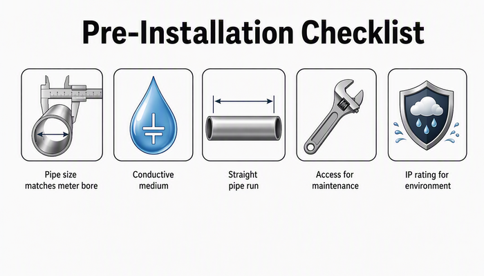
Good installations start before the flange bolts are tightened. Walk the site and confirm:
- The pipe size matches the meter bore, or the correct reducer/concentric transition is planned.
- The medium is conductive enough for mag metering (most water-based liquids qualify; non-conductive liquids such as pure hydrocarbons do not).
- The planned location allows the required straight pipe run upstream and downstream (see below).
- There is access for future maintenance, and space for the electronics housing to be opened and serviced.
- The environment suits the meter’s protection rating — for outdoor or wash-down areas, choose a meter with an adequate IP rating.
Taking fifteen minutes to verify these points prevents most installation-related performance problems.
Straight Pipe Requirements: Why They Matter and How Much You Need
An electromagnetic flow meter works by inducing a voltage in the flowing liquid, so in theory it is less sensitive to flow profile distortion than mechanical meters. In practice, however, strongly disturbed flow — caused by elbows, tees, pumps, valves, or reducers immediately upstream — creates swirl and asymmetrical velocity profiles that introduce measurement error.
The standard rule followed across the industry is:
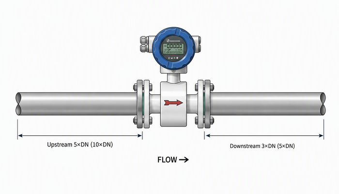
- Upstream straight pipe: typically 5 × DN (five times the nominal pipe diameter) is the common requirement, and many manufacturers specify 10 × DN for demanding installations.
- Downstream straight pipe: typically 3 × DN, and 5 × DN where space permits.
Always treat these figures as guidance and follow the value stated in the meter’s datasheet or installation manual. If a short straight run is unavoidable, discuss the options with the supplier — some modern transmitters offer flow-conditioning or profile-correction functions, but nothing replaces a proper straight run.
Position relative to pumps and valves:
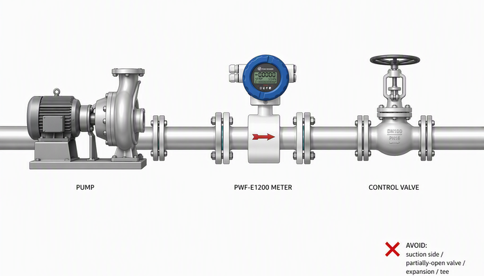
- Install the meter on the discharge side of pumps, not on the suction side where cavitation and pressure pulsation occur.
- Keep control and regulating valves downstream of the meter, so the meter always sees a full, stable flow.
- Avoid installing the meter immediately after a partially open valve, a pipe expansion, or a tee — these are classic error sources.
Grounding: The Most Overlooked Step in Mag Meter Installation
If there is one step that causes more field problems than any other, it is grounding. A mag meter generates a tiny signal voltage in the liquid, and that signal is easily corrupted by stray currents, electrical noise, or potential differences between the pipe and the liquid.
Why grounding rings or grounding electrodes are required: the measurement is made between two electrodes in contact with the liquid. For the sensor to detect only the induced signal — and not stray electrochemical or external interference — the liquid and the meter body must be at the same electrical potential. This is achieved by connecting the sensor to the process ground through grounding rings (for flanged meters) or a grounding electrode (for insertion and wafer types).
How to ground correctly:
- Use the grounding rings supplied with flanged mag meters, and connect them to the adjacent pipe flanges with the provided ground cables.
- Where the pipe is lined or non-metallic (e.g. plastic or rubber-lined pipes), grounding rings are mandatory — there is no metallic contact between the liquid and earth otherwise.
- Connect the ground terminal of the sensor and the converter to a clean earth point. Do not share the ground with motors, variable frequency drives (VFDs), or welding circuits.
- Keep ground cables short and heavy enough to carry fault currents.
A mag meter that measures erratically after installation is very often a mag meter that was never grounded properly.
Choosing the Right Mounting Position
Beyond the straight pipe run, the physical orientation of the meter determines whether it stays full of liquid and whether the electrodes stay clean.
Keep the pipe completely full. A mag meter must measure a full pipe; a partially filled pipe produces erratic readings. Practical rules:
- Avoid the highest point of the line, where air accumulates.
- On horizontal pipe, mount the meter so the electrodes are on a horizontal axis — i.e. the electrode plane is vertical. Electrodes pointing up collect air pockets; electrodes pointing down collect sediment.
- Vertical installation is perfectly acceptable and often preferred: flow upward, which keeps the pipe full and the electrodes submerged even at low flow rates.
Avoid these locations:
- Directly downstream of a free discharge (the meter must never see a falling stream).
- Positions where the pipe could run empty during normal operation.
- Locations near strong electromagnetic interference sources, such as large motors, transformers, or VFD cabinets.
Piping and Connections
Flange alignment and gaskets: align the pipe flanges so the meter body is not under bending or torsion stress — a distorted meter body can distort the liner. Use gaskets that match the full bore; a gasket protruding into the pipe creates turbulence and measurement error.
Liner protection: the liner (PTFE, PFA, rubber, etc.) is the mag meter’s wetted insulation. Do not drag the meter across rough surfaces during installation, and do not allow welding slag or debris to damage the liner face.
Integral vs. split versions: an integral (compact) mag meter like the PWF-E1200 series mounts the converter directly on the sensor — ideal for most indoor installations. For applications with high ambient temperature, strong vibration, or limited access — or where the display needs to be read from a convenient height — a split version like the PWF-E1200S separates the converter from the sensor and connects them with a signal cable. Check the maximum cable length in the datasheet and route the cable away from power lines.
Electrical Wiring and Signal Cable
- Route the signal cable separately from power and motor cables — never in the same conduit or cable tray.
- Use the shielded cable specified by the manufacturer and terminate the shield according to the wiring diagram (typically at one end, at the converter).
- For split versions, keep the converter–sensor cable as short as practical and protect it from mechanical damage.
- Verify the supply voltage and wiring against the nameplate before power-on.
Commissioning: First Power-On Checks
Before putting the line back into service:
1. Fill the pipe completely and check for leaks at flanges and electrode ports.
2. Check the empty-pipe detection: if the meter offers empty-pipe detection, verify it alarms when the pipe is empty and clears when full.
3. Verify zero: with the pipe full and flow stopped, the display should read zero (or a stable, negligible value). If not, re-check grounding before suspecting the meter.
4. Verify direction: confirm the flow arrow matches the actual flow direction.
5. Check the configuration: units, full-scale range, and output signal (4–20 mA, pulse, RS485, etc.) should match the control system’s expectations.
If readings are stable and repeatable after these checks, the installation is sound.
Common Installation Mistakes Specific to Mag Meters
While general sensor installation mistakes are covered in our earlier guide on the ten most common installation errors, mag meters fail for a few very specific reasons:
- No grounding rings on lined or plastic pipe — the single most frequent cause of noisy, drifting mag meter signals.
- Electrodes at the 12 o’clock or 6 o’clock position — air pockets or sediment covering the electrodes.
- Meter installed at a high point — partial fill and erratic readings.
- Insufficient upstream straight pipe — swirl and asymmetrical profile.
- Gaskets protruding into the bore — localized turbulence at the electrodes.
- Signal cable run alongside VFD or motor cables — induced noise.
None of these indicate a faulty meter. All of them are preventable during installation.
Pokcenser Electromagnetic Flow Meters for Reliable Installation
Pokcenser Automation designs its electromagnetic flow meters for real-world installations. The PWF-E1200 series provides reliable measurement for water treatment facilities, breweries, and milk processing plants, with a compact integral design that simplifies mounting in crowded plant rooms. Where heat, vibration, or access makes an integral unit impractical, the PWF-E1200S split-type keeps the converter where operators need it. For large municipal water supply, sewage treatment, and hydraulic engineering projects — where full-bore meters would be expensive and difficult to install — the PWF-E1700 insertion-type electromagnetic flow meter offers an economical, easy-to-install alternative on large-diameter lines.
Every Pokcenser mag meter ships with an installation manual and datasheet, and our engineers provide installation guidance for OEM and project customers. If you are unsure about straight pipe lengths, grounding arrangements, or sizing, ask before you install — it is cheaper than re-commissioning.
PREGUNTAS FRECUENTES
1. What is the minimum straight pipe length required before an electromagnetic flow meter?
The common industry requirement is 5 × DN upstream and 3 × DN downstream of the meter; some manufacturers specify 10 × DN upstream for demanding installations. Always follow the value stated in the meter’s datasheet. If space is tight, consult the supplier before installing.
2. Why does an electromagnetic flow meter need grounding?
The sensor measures a tiny voltage induced in the liquid. Without proper grounding, stray currents and potential differences between the pipe and the liquid corrupt the signal, causing unstable or drifting readings. Grounding rings or a grounding electrode put the liquid and the meter body at the same potential.
3. Can an electromagnetic flow meter be installed vertically?
Yes. Vertical installation with upward flow is often preferred because it keeps the pipe full and the electrodes submerged even at low flow rates. On horizontal pipe, mount the meter with the electrodes on a horizontal axis so they are not covered by air pockets or sediment.
4. How far can the converter be from the sensor on a split-type mag meter?
The maximum distance is defined by the manufacturer and stated in the datasheet (the PWF-E1200S split-type follows the datasheet specification). Keep the cable as short as practical and route it away from power and motor cables.
